Current Electricity Formulas
Electric Current is the movement of charges through the wire. If you need assistance regarding the Current Electricity Concepts then have a glance at Current Electricity Formulas. Make the most out of the Cheat Sheet on Current Electricity and get a good grip on the concepts. You can see various formulas like Ohm's Law, Drift Velocity, Current Density, Mobility, etc. Take your preparation to the next level by seeking help from the Physics Formulas and enhance your subject knowledge.
List of Current Electricity Formulae
1. Electric current
The rate of flow of charge
I = \(\frac{d q}{d t}\)
Unit → Ampere
2. OhmΓÇÖs law
If physical conditions (temperature, pressure etc.) of the conductor remaining unchanged then
V ∝ I or V = RI
3. Specific resistance (resistivity)
If l → length of conductor.
A → cross sectional area of conductor.
then
R = ρ \(\frac{\ell}{A}\)
Specific resistance ρ = \(\frac{R A}{\ell}\) ohm-m
The value of ρ depends only upon the nature of material and the temperature of the material.
4. Drift velocity
\(\overrightarrow{\mathrm{v}}_{\mathrm{d}}=\left(-\frac{\mathrm{e} \tau}{\mathrm{m}}\right) \overrightarrow{\mathrm{E}}\)
vd = \(\frac{\mathrm{eE} \tau}{\mathrm{m}}\)
where τ is relaxation time and m is the mass of electron.
If n is the number density of charge carriers (electrons), then the current
![]()
5. Current density (J)
J = \(\frac{1}{A}\) = nevd
= \(\left(\frac{\mathrm{ne}^{2} \tau}{\mathrm{m}}\right)\) E = σE
Conductivity
σ = \(\frac{J}{E}=\frac{1}{\rho}\) mho/m
![]()
Is another form of Ohm’s law.
6. Mobility (╬╝)
╬╝ = \(\frac{v_{d}}{E}=\frac{e \tau}{m}\) m2/V-s
7. Temperature dependency of resistance
Rt Γëê Ro (1 + ╬▒t)
╬▒ is called temperature coefficient of resistance
╬▒ = \(\frac{\mathrm{R}_{\mathrm{t}}-\mathrm{R}_{0}}{\mathrm{R}_{0} \mathrm{t}}\) per ┬░C
8. Combination of resistance
Series combination
R = R1 + R2 + ……… + Rn
Same current flows through all resistances.
In parallel combination
\(\frac{1}{R}=\frac{1}{R_{1}}+\frac{1}{R_{2}}+\ldots \ldots \ldots+1 / R_{n}\)
The potential difference across all resistances is same.
For two resistance in parallel.
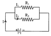
R = \(\frac{\mathrm{R}_{1} \mathrm{R}_{2}}{\mathrm{R}_{1}+\mathrm{R}_{2}}\) ; \(\frac{I_{1}}{I_{2}}=\frac{R_{2}}{R_{1}}\)
I1 = \(\frac{\mathrm{R}_{2}}{\left(\mathrm{R}_{1}+\mathrm{R}_{2}\right)}\) I, I2 = \(\frac{\mathrm{R}_{1}}{\left(\mathrm{R}_{1}+\mathrm{R}_{2}\right)}\) I.
9. KirchhoffΓÇÖs laws
First law (Current law or Junction law): At each node Σi = 0
i.e. i1 + i2 + i3 + ……… + in = 0
First law based on conservation of charge
Second law (Voltage law or loop law):
In each closed loop the sum of potential drops at different components in the direction of flow of current is equal to the total emf applied in the circuit.
ΣiR = Σ emf.
Second law based on conservation of energy
10. WheatstoneΓÇÖs bridge
In the balanced state of the bridge.
(Ig = o)
\(\frac{P}{Q}=\frac{R}{S}\)
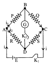
If \(\frac{P}{Q}>\frac{R}{S}\), VD > VB
If \(\frac{P}{Q}<\frac{R}{S}\), VB > VD
P.O. Box and Meter Bridge are also based on this principle.
11. Moving coil galvanometer
Coil (area A) suspended in a magnetic field (B) gets deflected when current is passed through the coil.
Deflecting couple niAB = restoring couple C╬╕
i = \(\frac{\mathrm{C} \theta}{\mathrm{nAB}}\) = K╬╕
Sensitivity = \(\frac{\theta}{i}=\frac{n A B}{C}\)
12. Ammeter
It is a current measuring device.
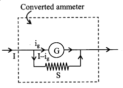
The shunt resistance S of an ammeter for range i ampere is –
S = \(\frac{\mathrm{i}_{\mathrm{g}} \times \mathrm{G}}{\left(\mathrm{i}-\mathrm{i}_{\mathrm{g}}\right)} \approx \frac{\mathrm{i}_{\mathrm{g}}}{\mathrm{i}}\) G
where ig is the current in the galvanometer for full scale deflection. S is a small (low) resistance connected in parallel.
The net resistance of an ammeter is \(\left(\frac{\mathrm{SG}}{\mathrm{S}+\mathrm{G}}\right)\)
13. Voltmeter
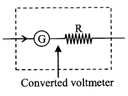
It is used for the measurement of potential difference. It is made by connecting proper high resistance in series with the galvanometer coil For a voltmeter of range V volt the value of resistance is
R = \(\left(\frac{\mathrm{V}}{\mathrm{i}_{\mathrm{g}}}-\mathrm{G}\right)\)
R → high resistance connected in series.
The net resistance of a voltmeter is (R + G)
14. Cell
It converts chemical energy into electrical energy.
Primary cell:
Chemical reactions are irreversible. Leclanche cell, Daniel cell etc.
Secondary cell:
Chemical reactions are reversible. After discharging, the cell can be recharged again. Lead accumulator, Alkali cell etc.
15. Electro motive force (E.M.F)
It is equivalent to the potential difference between the terminals of the cell when no current is drawn from the cell.
16. Terminal voltage (V)
It is the potential difference between the terminals of the cell when current is drawn from the cell.
V = E – IR (discharging), V = E + IR (charging)
17. Internal resistance (r)
It is due to collisions during the motion of ions in the electrolyte of the cell. It depends upon the natrue of electrolyte, temperature, current drawn and defects.
r = \(\frac{E-V}{I}\)
= \(\frac{E-V}{V}\)R.
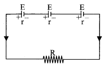
18. Grouping of cell
For n identical cells
Series grouping : I = \(\frac{n E}{R+n r}\)
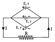
Parallel grouping: I = \(\frac{\mathrm{E}}{\mathrm{R}+\mathrm{r} / \mathrm{n}}=\frac{\mathrm{nE}}{\mathrm{nR}+\mathrm{r}}\)
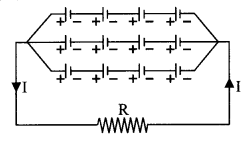
Mixed grouping: m rows of n cells, Total number of cells N = mn
I = \(\frac{n E}{R+n r / m}=\frac{m n E}{m R+n r}\)
For maximum current nr =mR.
19. Maximum power transfer theorem
- For maximum power transfer from a D.C. source:
- Load resistance R = internal resistance (r) of the source and maximum power is
P = \(\frac{E^{2}}{4 R}\)
20. Power dissipation in electrical circuit
P = VI = I2R = \(\frac{V^{2}}{R}\) watt
1 kWH (1 unit) = 1000 × 3600 Joule
For two bulbs of powers P1 and P2:
When connected in parallel with rated voltage:
P = P1 + P2
When connected in series with rated voltage:
\(\frac{1}{P}=\frac{1}{P_{1}}+\frac{1}{P_{2}}\)
or P = \(\frac{P_{1} P_{2}}{P_{1}+P_{2}}\)
Visit the one-stop destination for formulas i.e. Physicscalc.Com and clear all your ambiguities regarding different subjects.