Electro Magnetic Induction Formulas
Having full-fledged knowledge of the Electro Magnetic Induction Concept is necessary in order to solve the related questions. Keeping this in mind we have listed the Electro Magnetic Induction Formulas all in one place to make your calculations easy. Go ahead and refer to the Formula Sheet of Electro Magnetic Induction prevailing to learn the concepts underlying easily. You can get Formulas on Magnetic Flux, Faraday's Laws, Lenz's Laws, Induced EMF, etc.
Looking for help on more concepts then check out Physics Formulas Collection of ours to learn the topics efficiently.
Formulas Sheet for Electro Magnetic Induction
1. Magnetic flux
Φ = ∫
If the surface is closed, then
Φ =
because magnetic lines of force are closed lines and free magnetic poles do not exist.
B =
2. Electromagnetic induction: faradayΓÇÖs laws
(a) First law:
Whenever there is a change in the magnetic flux linked with a circuit with time, an induced emf is produced in the circuit which lasts as long as the change in magnetic flux continues.
(b) Second Law:
e ∝
3. LenzΓÇÖs law
The direction of the induced emf or current in the circuit is such that it opposes the cause due to which it is produced, so that,
e = – N
N → No. of turns in coil.
LenzΓÇÖs law based on energy conservation.
4. Emf current and charge induced in the circuit
(a) Induced emf e = – N
(b) Induced current I =
(c) Induced charge q = –
Induced charge depends only on net change in flux does not depends on rate of change in flux.
5. Emf induced due to linear motion of a conducting rod in a uniform magnetic field
e = –
If
e = Bvl volt
6. Induced emf due to rotation of a conducting rod in a uniform magnetic field
e =
where n is the frequency of rotation.
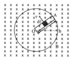
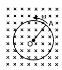
7. Induced emf due to rotation of a metallic disc in a uniform magnetic field
EOA =
here O is at higher potential then A (see fig.)
8. Induced emf, current and energy
Conservation in a rectangular loop moving in a non-uniform magnetic field with a constant velocity:
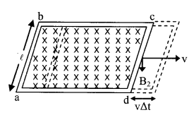
(i) Net increase in flux crossing through the coil in time Δt
╬ö╬ª = (B2 – B1) lv╬öt
(ii) Emf induced in the coil
e = (B1 – B2)l v
(iii) If the resistance of the coil is R, then the current induced in the coil
I =
(iv) Resultant force acting on the coil
F = I l (B1 – B2) (towards left)
(v) The work done against the resultant force
W = (B1 – B2)2
Energy supplied in this process appears in the form of heat energy in the circuit.
(vi) Energy supplied due to flow of current I in time Δt
H = I2R Δt
or H = (B1 – B2)2
or H = W
9. Rotation of rectangular coil in a uniform magnetic field
(a) Magnetic flux linked with coil
Φ = BAN cos θ
= BAN cos ωt
(b) Emf induced in the coil
e = –
(c) Current induced in the coil.
I =
=
(d) Emf and current induced in the coil are alternating emf and alternating current.
10. Self induction and self inductance (L)
On changing the current in a coil, a induced e.m.f. is produced in the coil I NOTES then the phenomenon is called self induction j
(i) Φ ∝ I or Φ = LI
or L =
(ii) e = – L
where L is a constant, called self inductance or coefficient of self-induction.
or L =
(iii) Self inductance of a circular coil
L =
(iv) Self inductance of a solenoid
L =
(v) Two coils of self inductances L1 and L2 placed far away (i.e. without j coupling) from each other
(a) For series combination: j
L = L1 + L2 …. Ln
(b) For parallel combination:
11. Mutual induction and mutual inductance
(a) On changing the current in one coil, if the magnetic flux linked with a § second coil changes and induced e.m.f. is produced in that coil, then this phenomenon is called mutual induction.
(b) Φ2 ∝ I1 or Φ2 = MI1
or M =
(c) e2 = –
(d) M12 = M21 = M
(e) Mutual inductance of two coaxial solenoids
M =
(f) If two coils of self inductance L1 and L2 are wound over each other, the mutual inductance is given by
M =K
where K is called coupling constant.
(g) For two coils wound in same direction and connected in series
L = L1 + L2 + 2M
For two coils wound in opposite direction and connected in series
L = L1 + L2 – 2M
For two coils in parallel
L =
12. Energy stored in an inductor
Energy stores in the form of M.F.
UB =
Magnetic energy density
UB =
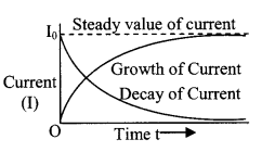
13. In L-R circuit
- Growth of current I = I0 (1 – e-Rt/L)
- Decay of current I = I0 e-Rt/L
- Time constant τ = L/R

14. Eddy current
When a conductor is moved in a magnetic field, induced currents are generated in the whole volume of the conductor. These currents are called eddy currents.
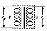
15. Transformer
(a) It is a device which changes the magnitude of alternating voltage or current.
(b)
(c)
(d) In an ideal transformer:
= epIp = esIs or pin = pout
(e) In step-down transformer:
Ns > Np or K > 1
es > ep and Is < Ip
(f) In step-down transformer:
Ns < Np or K < 1
es < ep and Is > Ip
(g) Efficiency ╬╖ =
16. Generator or dynamo
It is a device by which mechanical energy is converted into electrical energy. It is based on the principle of E.M.I.
17. Ac generator
It consists of field magnet, armature, slip rings and brushes. The frequency of voltage generated by it is –
f =
N → No. of pole
n → frequency of rotation
18. Dc generator
It consists of field magnet, armature, commutator and brushes.
19. Motor
It is a device which converts electrical energy into mechanical energy.
Back emf e ∝ ω
Current flowing in the coil
ia =
or e = eb + iaR
where R is the resistance of the coil.
Out put Power = iaeb
Efficiency ╬╖ =
Explore Various Concepts Formula for the Subject Physics all at Physicscalc.Com and clear all your queries and improve your skills.