Crossover Calculator
Crossover Calculator is a handy tool that helps you design amazing sound speakers. Determine the capacitors and inductors you need to create a passive crossover design for your speakers using the Crossover Calculator. Simply provide the inputs as in the tool and tap on calculate button to avail results in the blink of an eye.
Crossover Calculator: Do you want any assistance to decide on the best crossover design for your speakers? If so, you have landed on the rigt page that gives you clear idea on passive crossover design. Learn why you need more than one speaker inorder to obtain better sound and the right electornic components needed to send most apt frequencies to the speaker. Also, learn about several circuits that stabilize speaker's impedance as frequency changes(Zobel), another model that attenuates the volume(L-Pad).

Why more Speakers are Better than One?
Are you wondering why you need more speakers for better sound? Single Speaker may not sound properly in all the frequencies and this is the common complaint regarding single speakers. They lack in bass response and have sound distortions at low frequencies and has low volume. You can resolve this issue by making the speaker bigger. However, doing so would result in low volume at high frequencies. In Case of a hi-fi speaker design, we look for same sound volume across a wide range of frequencies.
You can overcome this problem by having more speakers in the speaker unit. Speaker that results in high frequencies is known as tweeter and the ones that produces low frequencies is known as woofer. In Case of a three-speaker set up you will have a mid range speaker that covers range of frequencies between high quality tweeter and low quality woofer speakers.
There is a problem with this multiple speaker set up too when connected to an amplifier. The speaker cable has all frequencies thus the woofer still get high frequencies and tweeter gets low frequencies. Frequency Mismatch produces sound distortion and can even damage the speakers at times if it gets a loud signal at wrong frequency.
Passive Crossover Design
One Solution to overcome the problem of sound distortion is to split up the signals coming from amplifier as per the sound frequency. Using right combination of tweeters and woofers will allow right range of frequencies to reach the speaker. If Two-Speakers are involved then it is said to be a 2-Way Passive Crossover Design and in case of 3 Drivers it is called a 3-Way Passive Crossover. It is named passive since it needs no additional power source required by the speaker.
You can also use another alternative for the sound distortion problem i.e. active cross design in which you split up the signal before amplification itself. In case of 2-way cross over designs you will have both low-pass and high-pass crossover filters. Low Pass Filter will allow frequencies below certain limit and a high pass filter allows frequencies after certain limit. Crossover frequency is where low-pass begins to fade and high pass starts increasing the signal amplitude. A 3-way cross over design adds a band pass filter that selects mid range frequencies for midrange speaker.
Physicscalc.Com has got concepts like friction, acceleration due to gravity, water pressure, gravity, and many more along with their relevant calculators all one under one roof.
Order and Filter Type
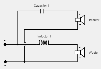
You can choose the order of the crossover as well as the filter characteristic. Of all the orders the simplest one is a 1st Order Crossover Design and has only one capacitor and one inductor. It has a 6dB/Octave Slope and it is the lowest possible slope. Based on the value of the slope you can learn how attention the filter is applying with change in frequency. There is a mininum power loss in this case. However, there still can be a chance of wrong signals entering the speaker and leads to damage. Check out further sections to have an overview of some of the higher order filters and their characteristics.
Second Order Crossover Design
- It has 12dB/Octave Slope and allows more attenuation of unwanted signals
- It is the most commonly used design as it very few components
- Enough Protection for the High Frequency Tweeter-Driver
- You can choose wide range of filter characteristics such as Butterwork, Bessel, Linkwitz, and Chebyshev
Third Order Crossover Design
- It has 18dB/Octave Slope and provides even more attenuation for out-of-band frequencies.
- It has significant power loss
- Supports Butterworth or Bessel filter characteristics.
Fourth Order Crossover Design
- 4th order crossover design has a very steep slope of 24dB/Octave
- It is a bit complicated design as it includes more components
- Components might interact with each other and affects sound quality.
- Has noticeable power loss which reduces speaker's sound level.
2-Way Passive Crossover Design Formula
Learn how to calculate 2-way cross over design having butterworth filter characteristics including two capacitors and two inductors. The formulas for finding all 4 components are given as under
- capacitor 1 = 0.1125 / (tweeter impedance * crossover frequency)
- capacitor 2 = 0.1125 / (woofer impedance * crossover frequency)
- inductor 1 = 0.2251 * tweeter impedance / crossover frequency
- inductor 2 = 0.2251 * woofer impedance / crossover frequency
The equations for other higher order filters are same as above but has varying constant.
Additional Circuits - Zobel and L-Pad
On selecting the number of speakers in calculator to one you can choose from two different circuits that has a single speaker namely Zobel and L - Pad.
Zobel Circuit: In this the Speaker has a Coil of Wire which acts an Inductor. This results in speaker's impedance to change with change in frequency of sound. The Solution is to use a Zobel Circuit between crossover circuit and speaker and stabilizes the speaker's impedance as seen in the case of crossover circuit.
Zobel Circuit is simple and includes a resistor and capacitor wired in parallel to the speaker. Formulas for finding the values in the Zobel Circuit is given by Rz = 1.25 * Rs and Cz = Ls / Rz2
- Where Rz is the resistor value in the Zobel Circuit
- Rs is the Speaker's Resistance
- Cz is the Capacitor Value in the Zobel Circuit
- Ls is the Speaker Inductance
L-Pad Circuit: This Circuit attenuates the signal to a speaker and has two resistors arranged in the letter "L". The formulas for determining the two resistors is given by R1 = Zs * ((10(Loss/20) - 1)/10(Loss/20)) and R2 = Zs / (10(Loss/20) - 1)
- Where R1 is the Series Resistor
- Zs is the Speaker's Impedance
- Loss is the signal's attenuation in dB
- R2 is the Parallel Resistor
Frequently Asked Questions on Crossover Calculator
1. What does a Zobel Network do?
Zobel Network is used to flatten a driver's impedance and makes a filter more effective.
2. How is Zobel Network Calculated?
You can calculate capacitor and resistor in Zobel Circuit by the formulas Rz = 1.25 * Rs and Cz = Ls / Rz²
3. What are different types of crossover designs?
There are several types of crossover designs such as 2-way crossover design, 3-way crossover design, 4-way crossover design and many others.
4. How to use a Crossover Design Calculator?
All you need to do is simply type in the necessary inputs such as number of speakers, filter order & characteristic, crossover frequency, tweeter and woofer impedance, etc. and click on the calculate button to get respective outputs in no time.